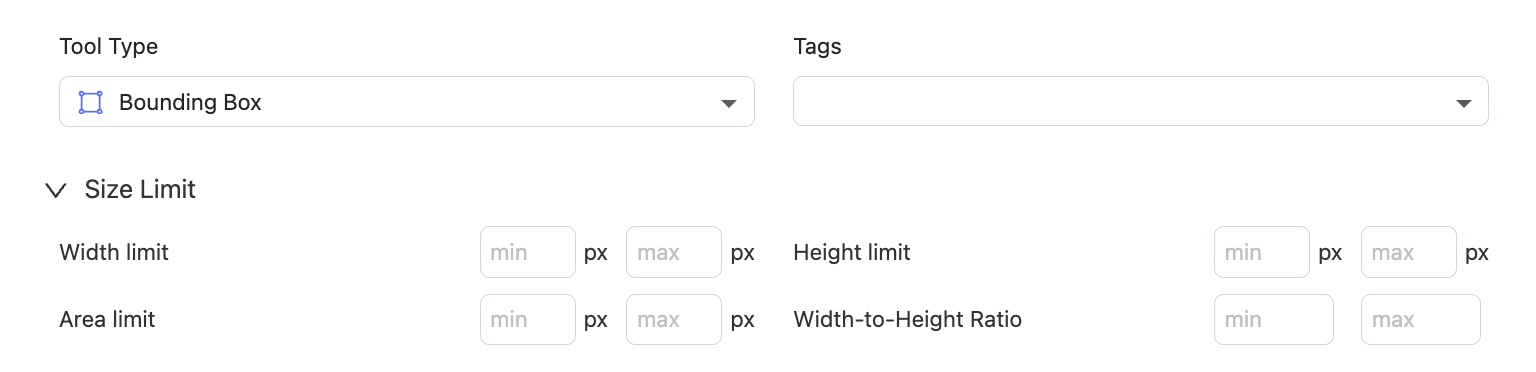
Tool Type
Image 🌄
Bounding Box
Draw rectangles around objects; commonly used for object detection.

Preview in Tools
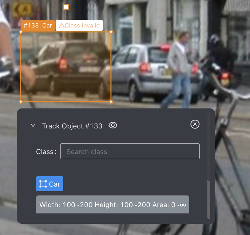
- Size Limit (optional): Set limits for the Width, Height, Area, and Width-to-Height Ratio of the bounding box. A "Class Invalid" error will be displayed if the result fails to meet these limits.
Config in Ontology
Preview in Tools
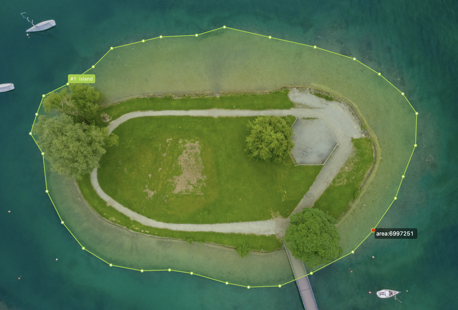
Polygon
Outline irregular shapes by connecting multiple points; commonly used for annotating objects with intricate boundaries.
Preview in Tools
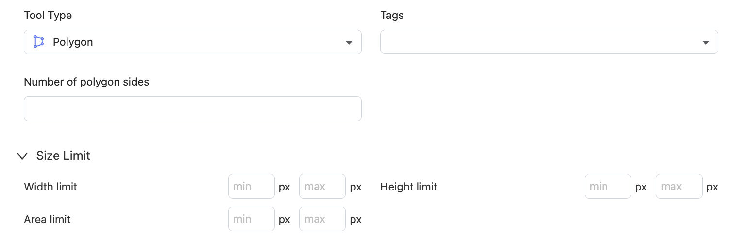
- Number of polygon sides (optional): Specify the number of sides for the polygon (minimum 3) and add a new tool labeled "polygon+number" to the toolbar. When using this tool for drawing, the shape will automatically close once annotators reach the designated number of sides.
Preview in Tools
- Size Limit (optional): Set limits for the Width, Height, and Area of the polygon. A "Class Invalid" error will be displayed if the result fails to meet these limits.
Config in Ontology
Polyline
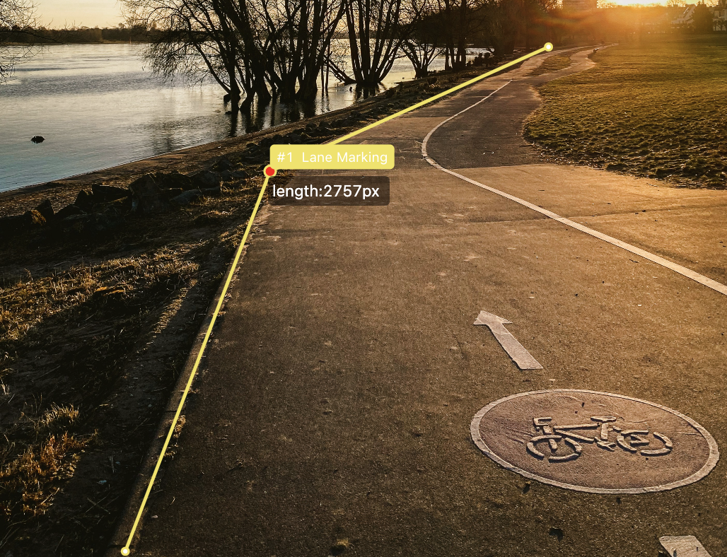
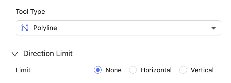
Annotate lines in images; commonly used for road tracking or annotating object contours.
Preview in Tools
- Direction Limit (optional): Set whether the polyline needs to align with the Horizontal or Vertical axes. A "Class Invalid" error will be displayed if the result fails to meet this limit.
Config in Ontology
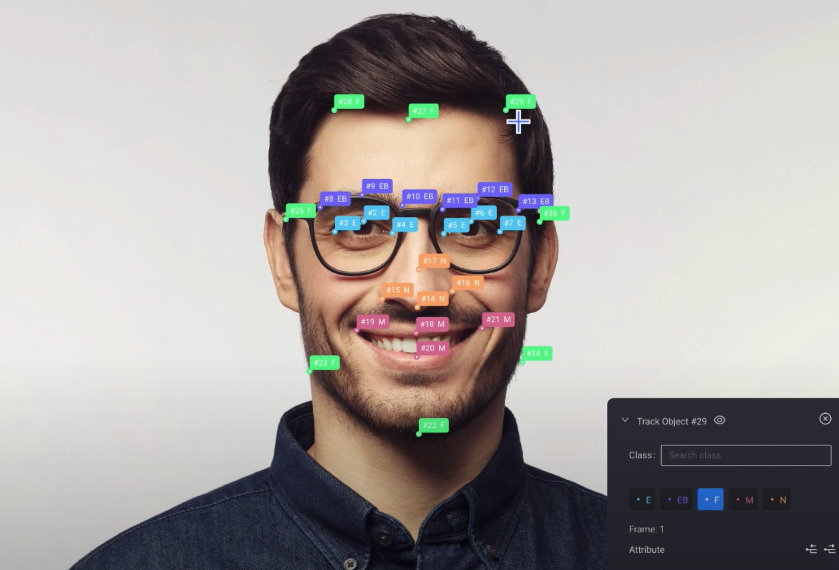
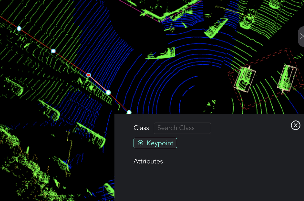
Keypoint
Mark specific points on objects, such as facial landmarks or joints on the human body.
Preview in Tools
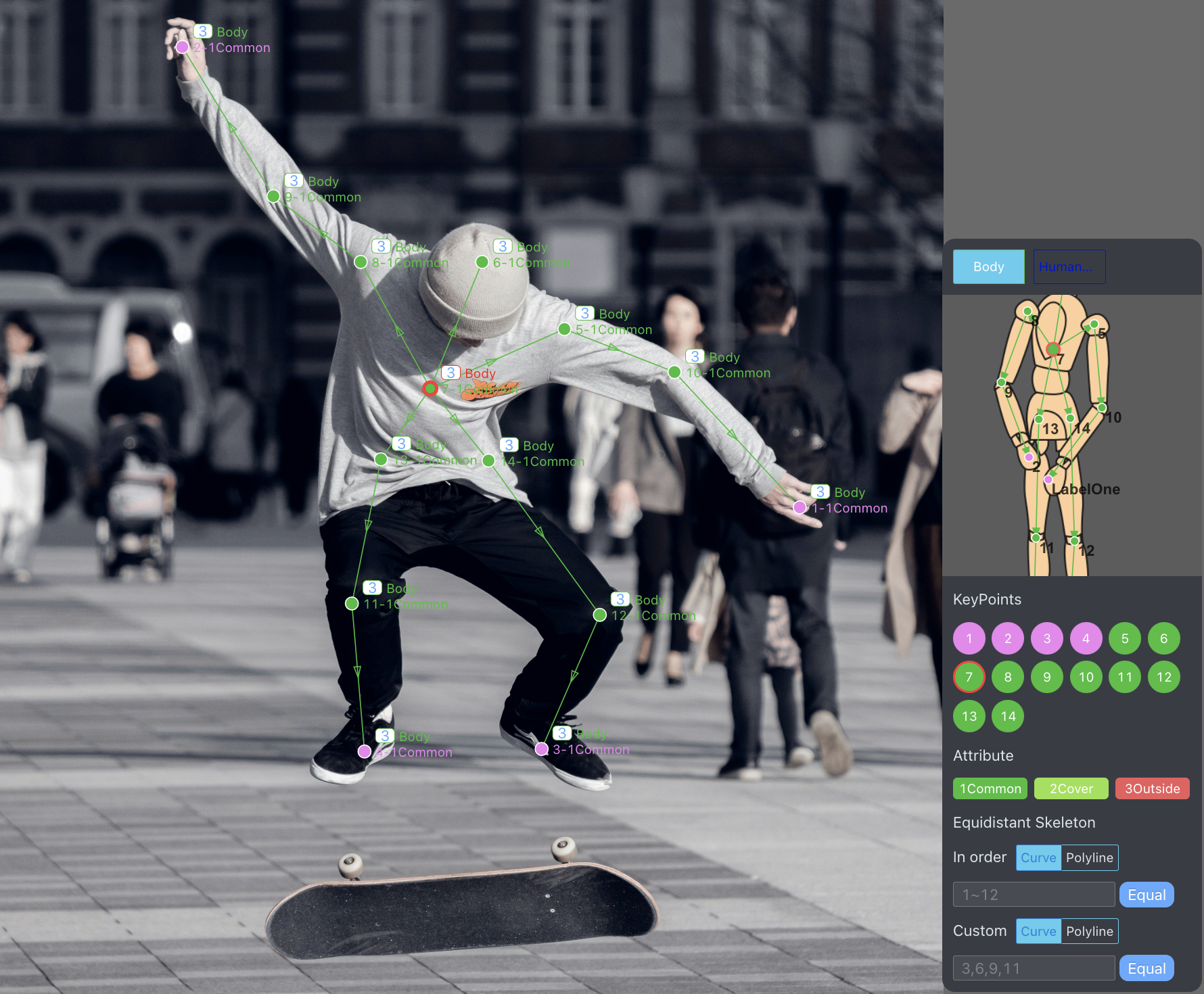
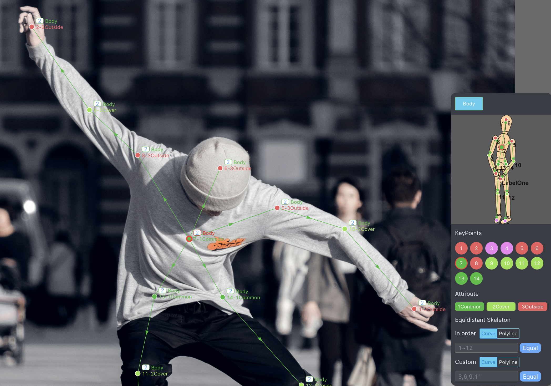
Skeleton
Form a skeletal structure by connecting key points on the human body, typically at joint locations such as elbows, knees, shoulders, and hips; commonly used in human pose estimation.
Preview in Tools
After selecting Skeleton as the tool type, you need to complete the reference image showing the points to be annotated.
💡Steps to Configure the Skeleton Tool
1. Basics
🖱️Right click and hold to drag the image. Zoom in/out with your mouse scroll wheel. 🖱️Left click to select a point or line.
By default, points and edges have the same color as the class. You can change them individually on the right, or modify the colors of existing points and edges in the left list.
You can also customize the reference image by clicking the Update Picture button.
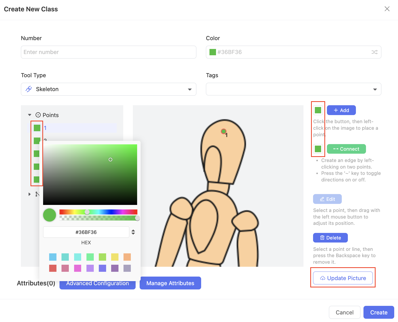
2. Points
Create: Click the Add button, then 🖱️Left click on the image to place a point.
Edit: Click the Edit button. Select a point on the image or the left list, then hold down 🖱️Left click to drag and adjust its position.
Delete: Click the Delete button, then select a point and press the Backspace key to remove it. Alternatively, you can also delete it from the left list.
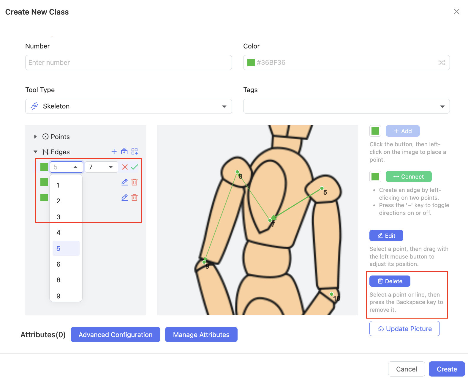
3. Edges
Create an Edge by Two Nodes: Click the Connect button, then 🖱️Left click on two points to create an edge. Press the ~ key to toggle directions (from the start to the end node) on or off. You can also click the icon on the left list to create an edge by selecting two nodes.
Create Multiple Edges Sequentially: Click the icon on the left list to select the start and end nodes. It will automatically connect the points between them in sequence.
Create Multiple Edges in a Custom Order: Click the icon on the left list to enter node numbers separated by ",". It will connect the nodes in order automatically.
Edit: Select an edge on the left list, then click the edit icon to modify the start and end nodes.
Delete: Click the Delete button, then select an edge and press the Backspace key to remove it. Alternatively, you can also delete it from the left list.
4. Advanced Configuration
Optionally, you can click the Advanced Configuration button to set up extra details about the tool.
Keypoints Label: Enter a label for each point (displayed as a number by default). Each label should be under 255 characters and must not be duplicated.
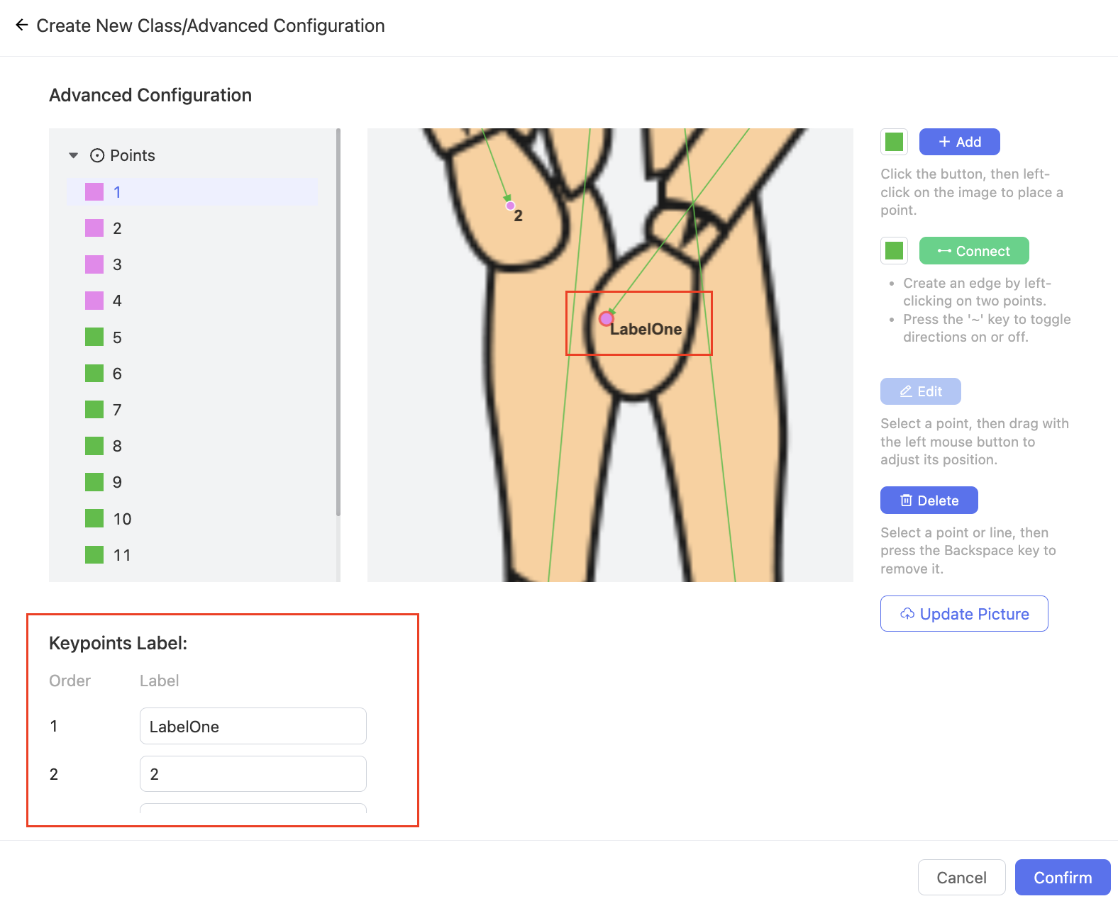
Equidistant Skeleton: Click the In Order button to set the start and end nodes, or click the Custom button to enter a list of node numbers separated by ",". When annotating in Tools, the points will be evenly distributed along the drawn curve or polyline based on the settings.
Preview in Tools
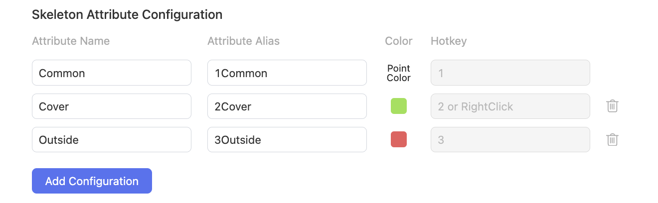
Skeleton Attribute Configuration: In addition to class attributes, you can also set attributes for each point in the skeleton, including Name, Alias, Color, and Hotkey (automatically configured in sequence from 1 to 9 and 0).
Config in Ontology
Preview in Tools
Curve
Outline objects with complex curved shapes such as road bends, natural contours, and medical imaging vessels.
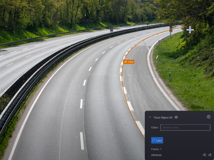
Preview in Tools
Group
Organize and group related results for improved management and understanding of complex scenes.
Preview in Tools
Mask
Create masks to cover specific areas in images; commonly used for Segmentation.
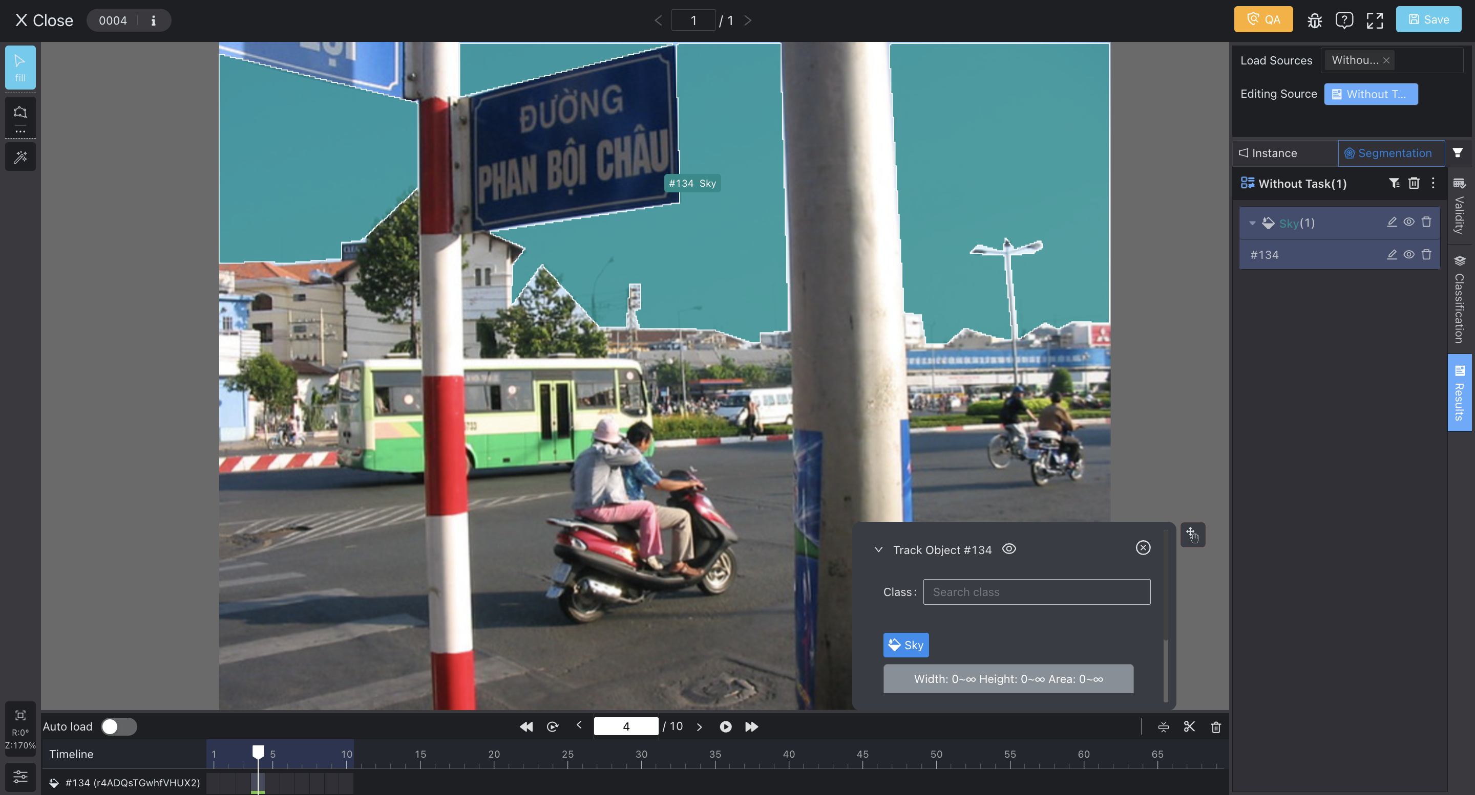
Preview in Tools
- Size Limit (optional): Set limits for the Area of the mask. A "Class Invalid" error will be displayed if the result fails to meet these limits.
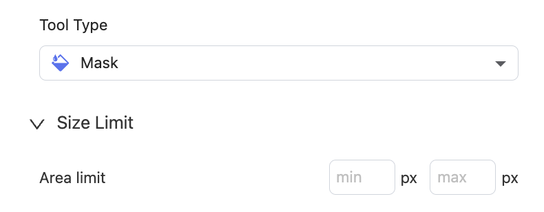
Config in Ontology
Cuboid
Construct a pseudo-3D cuboid around objects by drawing two rectangles; commonly used for annotating objects with depth information.
Preview in Tools
Circle
Mark circular objects or regions in images.

Preview in Tools
Ellipse
Annotate elliptical shapes in images, useful for objects with oval or elliptical structures.

Preview in Tools
LiDAR Fusion 🌌
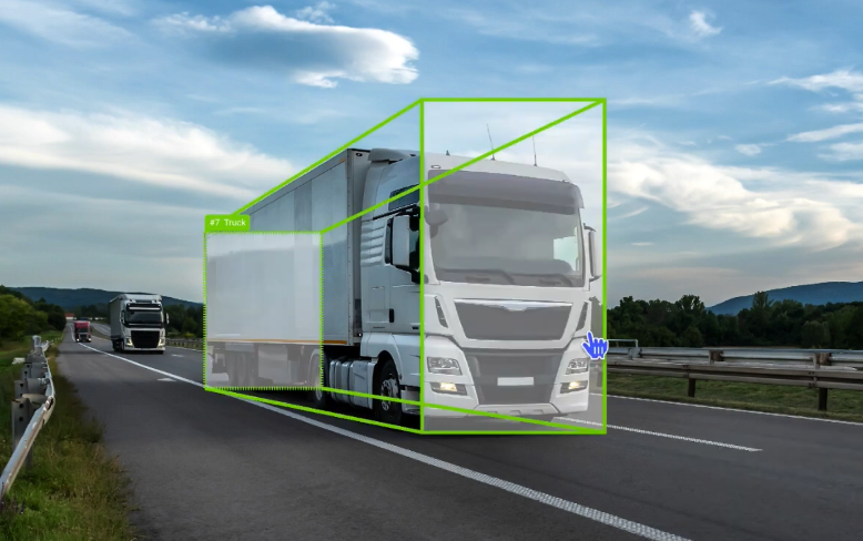
Cuboid
Draw 3D bounding boxes around objects, typically for annotating the position, size, and orientation.
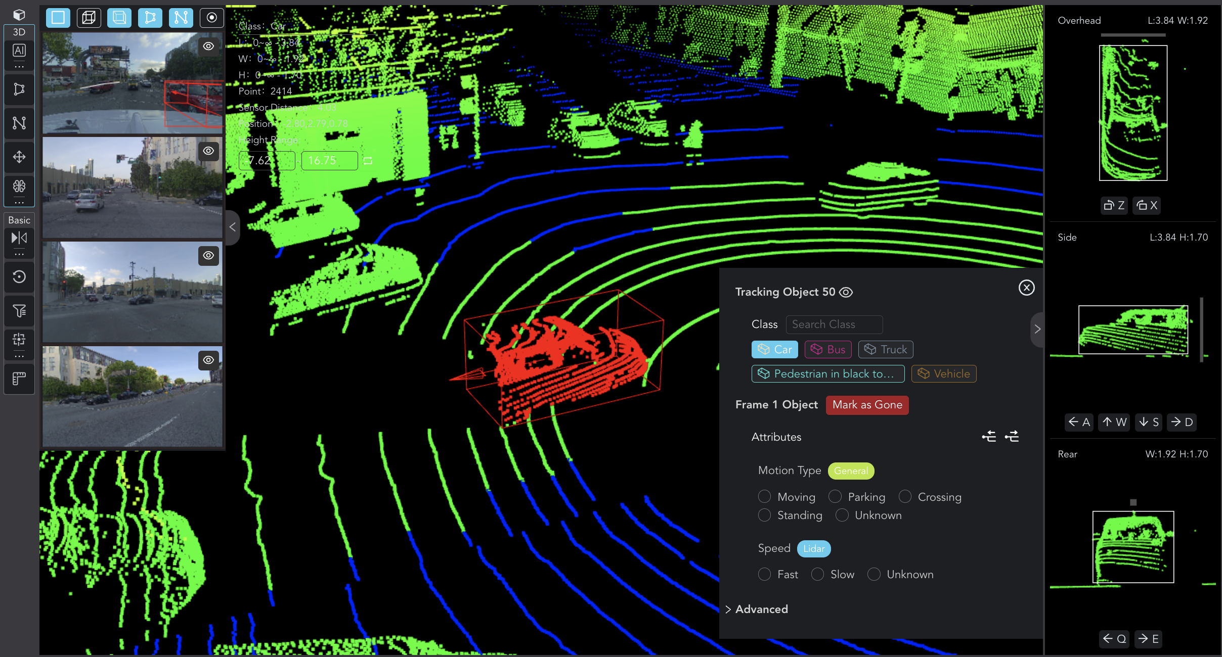
Preview in Tools
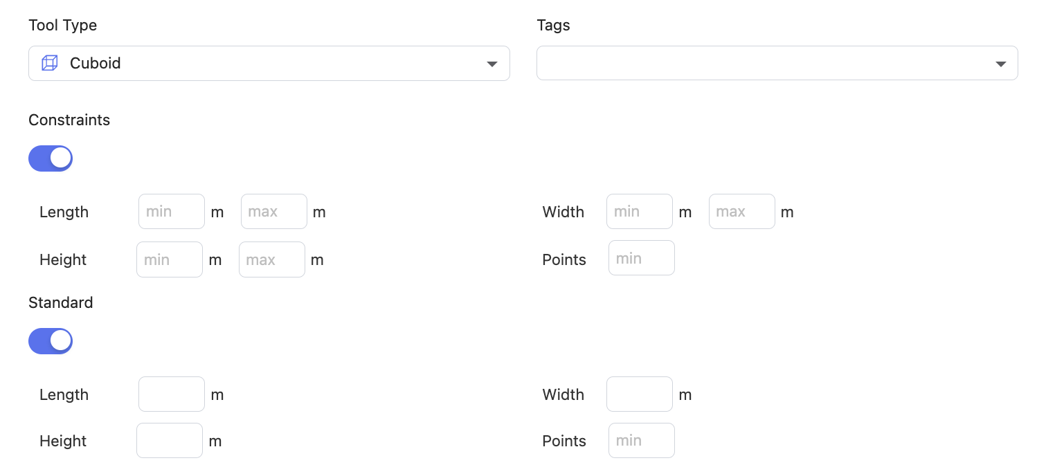
- Constraints (optional): Set limits for the Length, Width, Height, and Points of the cuboid. An error will be displayed if the result fails to meet these limits.
- Standard (optional): Set the standard Length, Width, Height, and Points of the cuboid used for this class as a reference for annotators.
Segmentation
Annotate objects or regions in point clouds by segmenting them into different categories or objects.
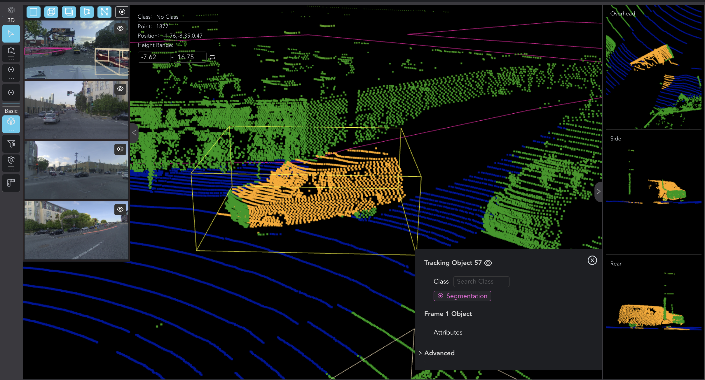
Preview in Tools
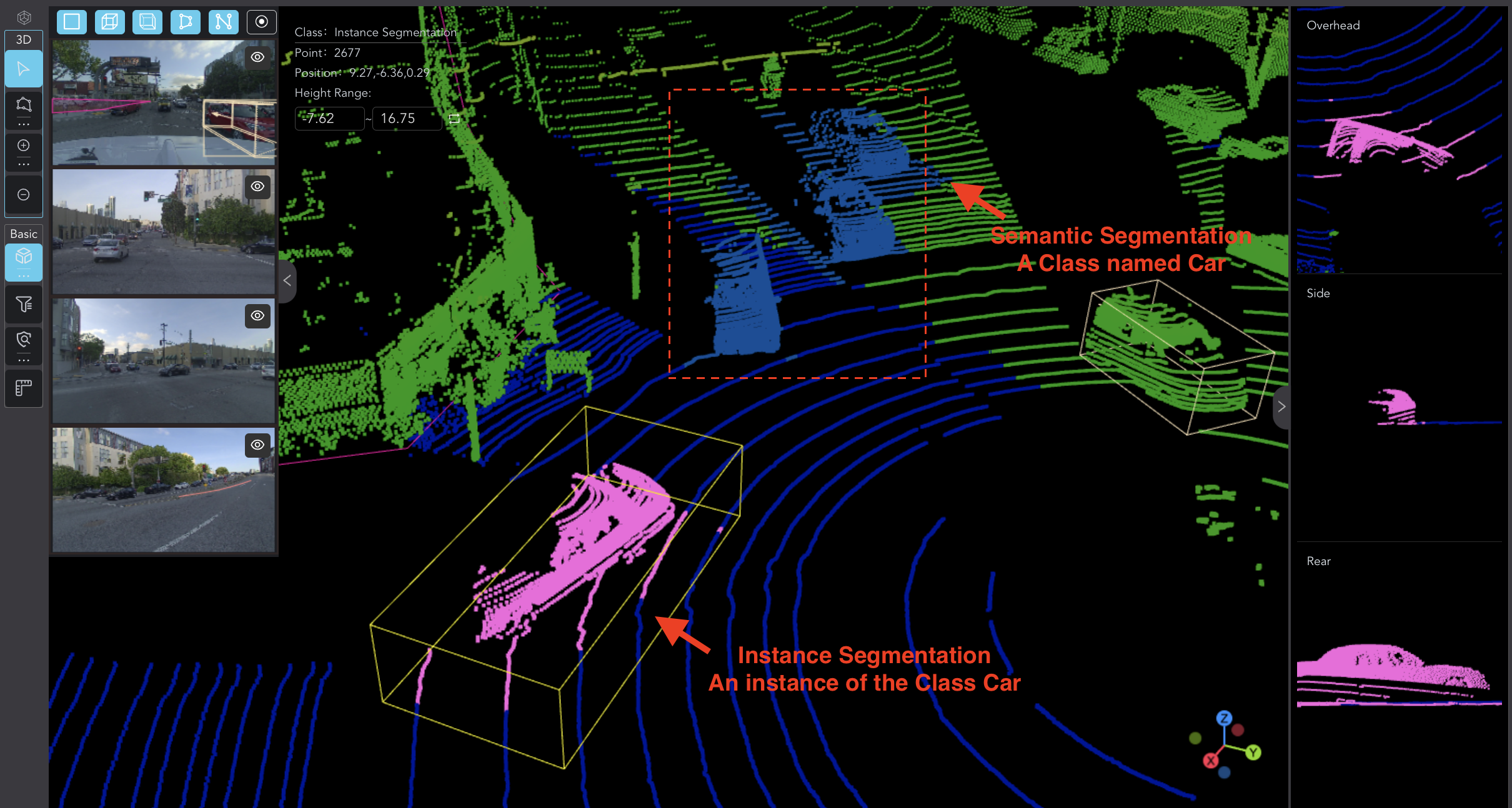
- Result Type (required): Specify whether the annotation result should be Instance Segmentation or Semantic Segmentation.
Semantic segmentation involves labeling each point in data with a class label without distinguishing between different instances of the same class.
Instance segmentation goes a step further by not only categorizing each point but also distinguishing between different instances of the same class.
Preview in Tools
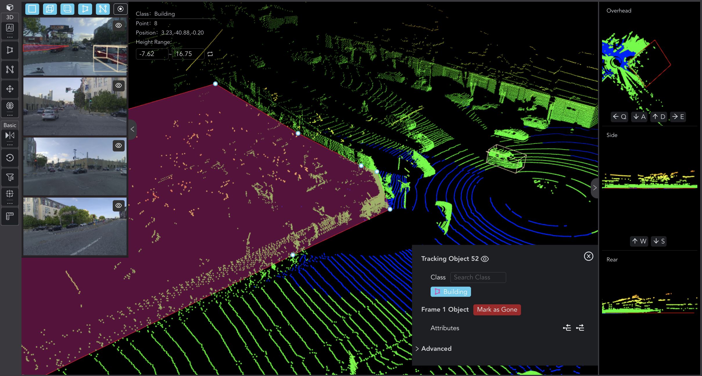
Polygon
Draw polygonal areas on a plane; commonly used for annotating object contours or irregular shapes.
Preview in Tools
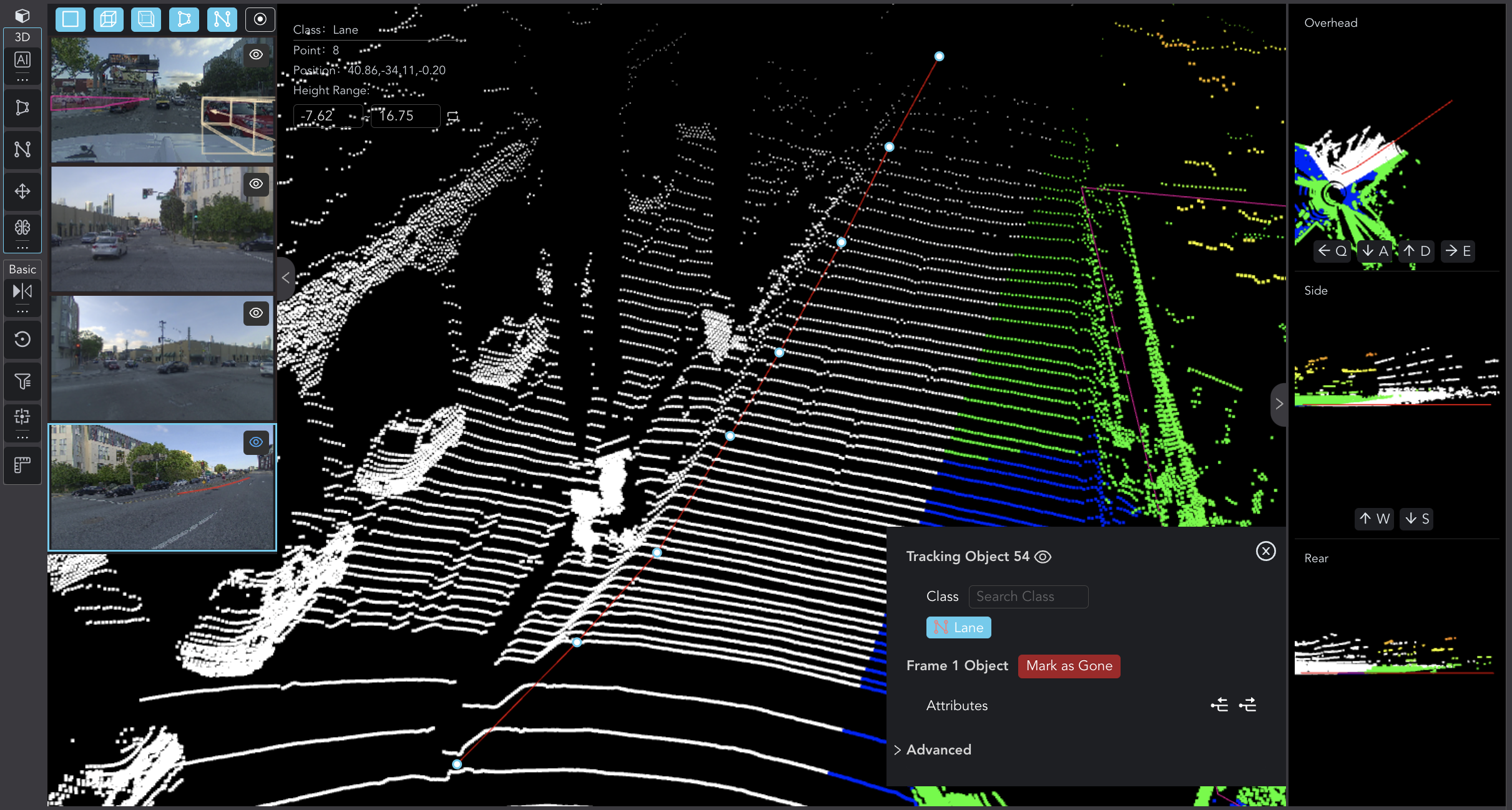
Polyline
Annotate lines in point clouds; commonly used for representing linear objects like roads, pipelines, etc.
Preview in Tools
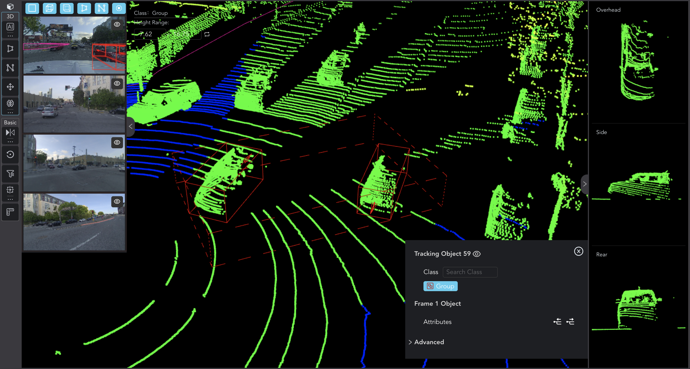
Group
Organize and group related results for improved management and understanding of complex scenes.
Preview in Tools
Keypoint
Annotate points on a drawn polyline or polygon.
Preview in Tools
Audio & Video 🎥
Clip
Trim and segment media files, allowing for accurate labeling of specific sections or events within the content.
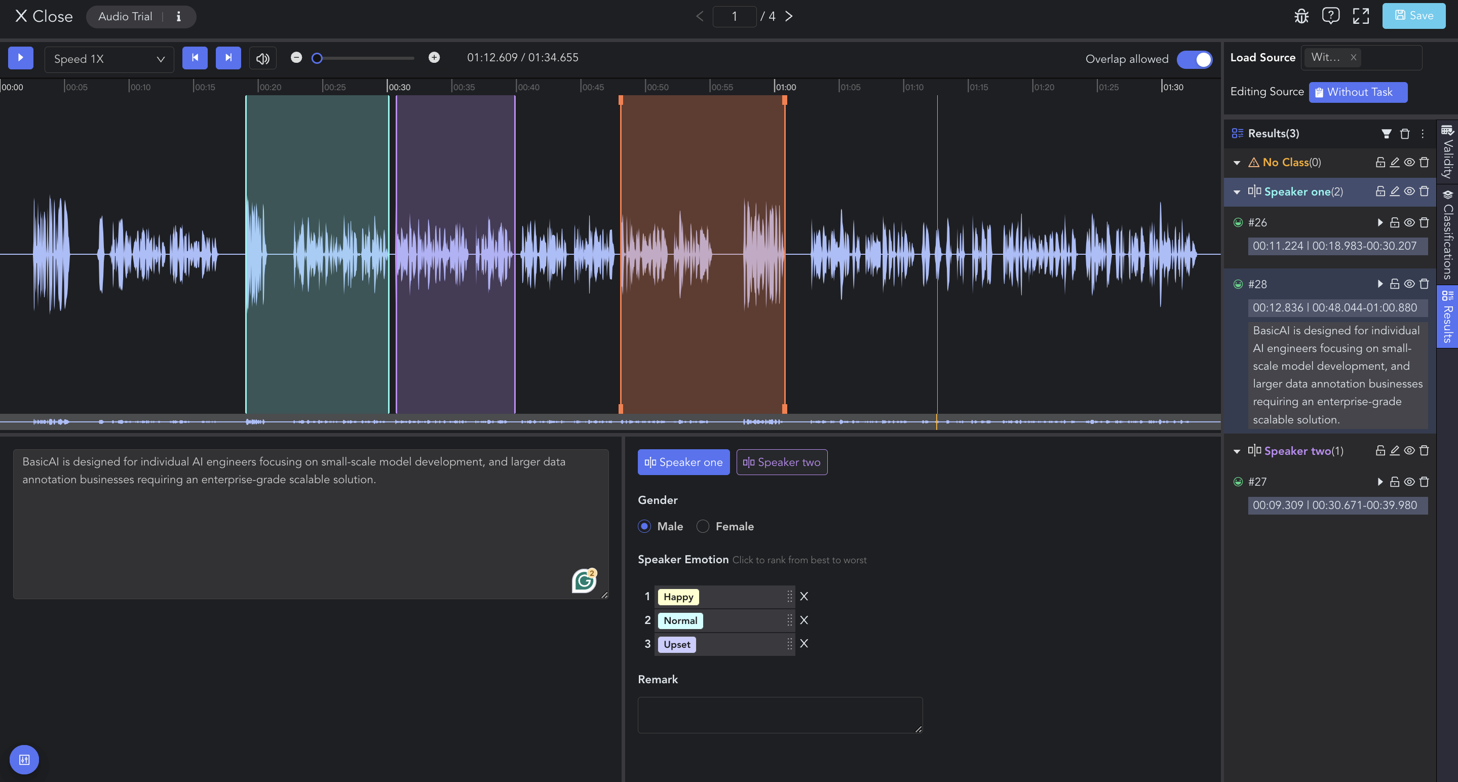
Preview in Tools
- Length Limit (optional): Set the length limit of the clip. An error will be displayed if the result fails to meet these limits.
Text 📄
Entity
Annotate text entities in textual data by selecting/double-clicking words or sentences and choosing the class & attribute on the tool page.
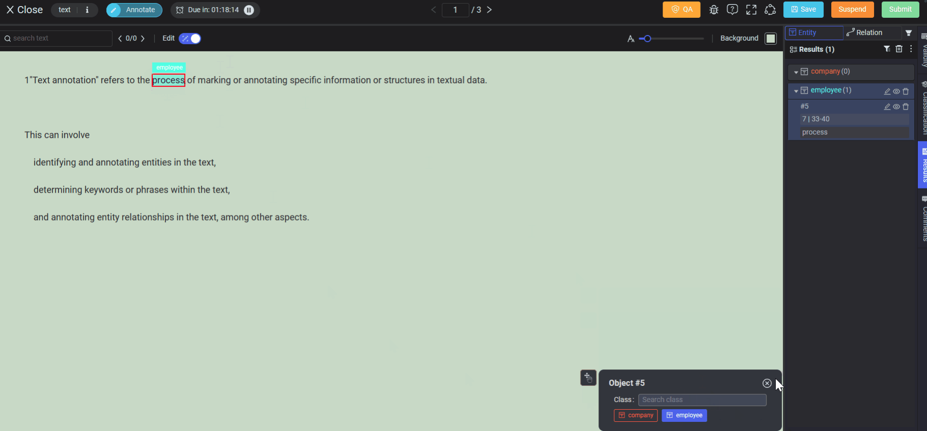
Preview in Tools
Relation
Annotate relations between selected text entities by connecting the start entity to the end entity and choosing the class & attribute on the tool page.
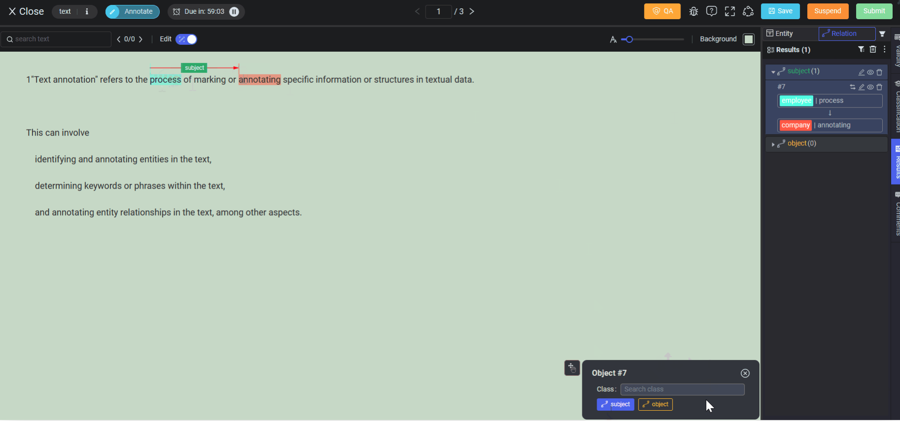
Preview in Tools
When configuring ontology class and classification, after choosing the Relation tool, you need to add the Qualified Entity and select starting/ending entities for workers to mark relations in textual data.
Class Setting
Generative AI 🤖
Dialog Evaluation
This tool is designed for RLHF Dialogue Evaluation annotaion. On the tool page, hover or click on a conversation bubble and then select the class & attribute for the conversation contents between the User and Bot.
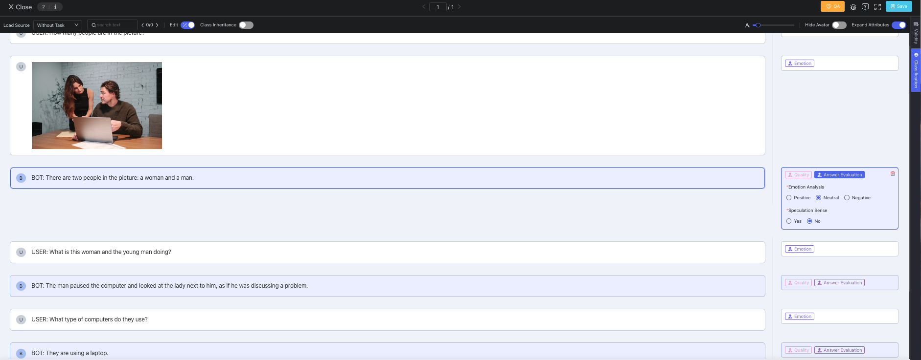
Preview in Tools
When configuring ontology class & classification for a Generative AI dataset, after choosing the Dialog Evaluation tool, you also need to choose which is the target of evaluation: User or Bot. Attribute Management section has the same logic as other kinds of datasets.
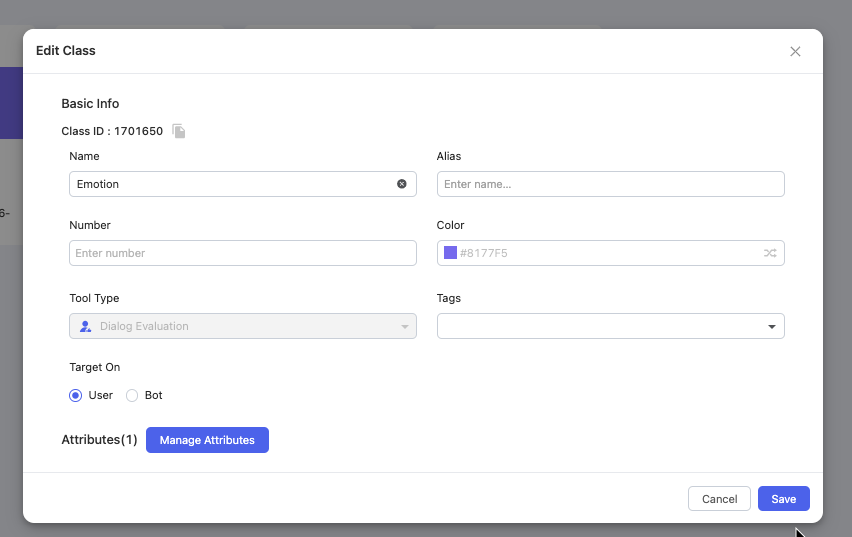
Class Setting
Dialog Response
It is designed for SFT Dialogue Response annotation. The configured classes are located at the bottom left of the tool page. Click on one class, and then type in your response in the text box without the need to select any conversation bubble on the data canvas.
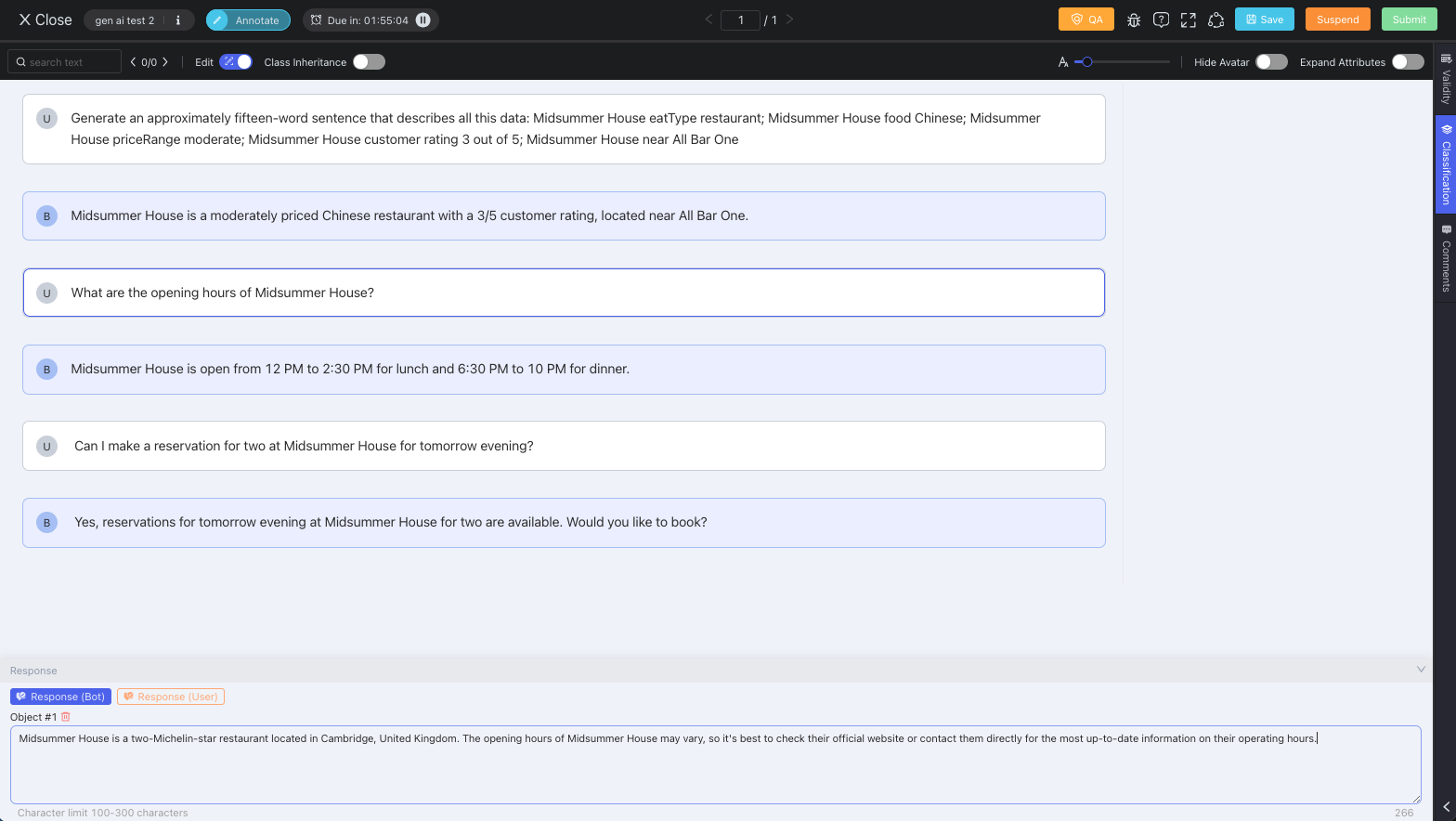
Preview in Tools
When configuring ontology class & classification, after choosing the Dialog Response tool, select to response as User or Bot, and then define the character constraints from Min xx Char to Max xx Char.
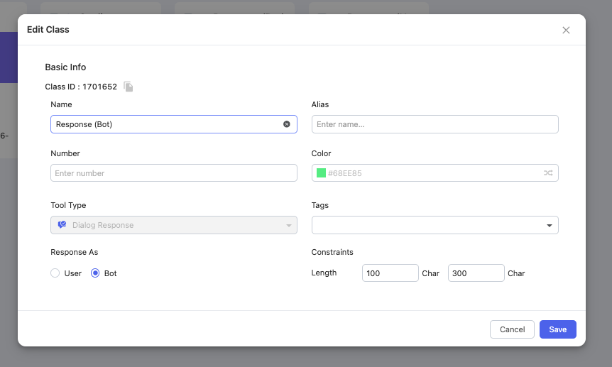
Class Setting
Updated about 1 year ago