Camera Intrinsic, Extrinsic and Distortion in Camera Calibration
📷 Introducing camera calibration parameters and configuration in the LiDAR Fusion annotation tool.
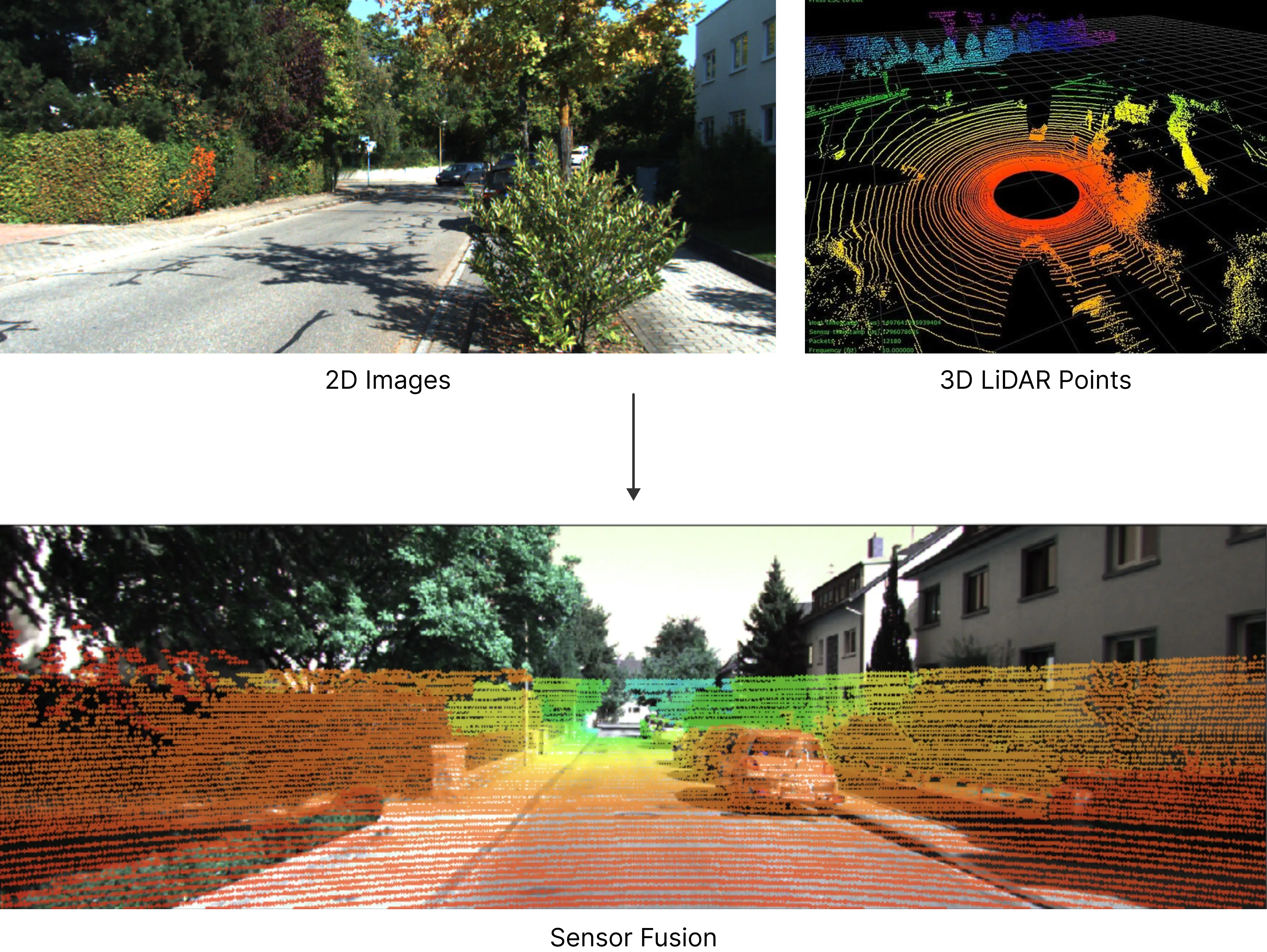
In 2D and 3D sensor fusion annotation, Camera Calibration determines how accurately 3D LiDAR points map to pixels in the 2D images, on which all projection-related features of the BasicAI's LiDAR fusion tool depend.
In this article, we will explain the principles of 3D-to-2D projection and demonstrate how to calibrate the camera, including intrinsic and extrinsic parameters, distortion coefficients, etc.
Project 3D to 2D Overview
The commonly used coordinate systems in sensor fusion are listed below. For more details, you can click on each to expand.
🌍 **Radar/Point Cloud Coordinate System (3D)**
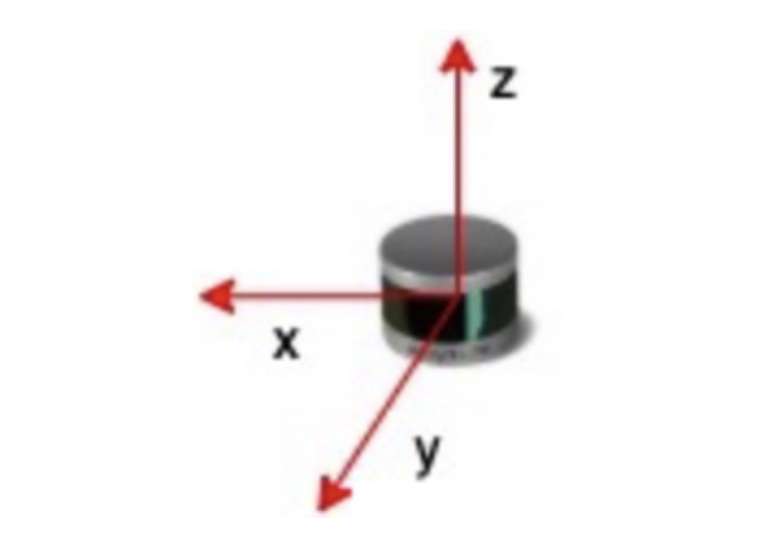
This is a coordinate system based on the radar sensor:
- X-axis: directly in front of the radar
- Y-axis: left side of the radar
- Z-axis: above the radar
P=(Xw, Yw, Zw) are the coordinates of a 3D point in point cloud data.
NotesThe X-axis direction represents the radar's front, not the car's. However, in common autonomous driving systems, the radar's X-axis points directly ahead of the car, with the X-axis denoting the car's front direction.
World Coordinate SystemIn most references, 3D points are usually represented in the world coordinate system. It's important to note that the world coordinate system is stationary, while the radar coordinate system is sensor-based and may not align with the world coordinates. In the BasicAI fusion annotation tool, we simplify and treat the two as equal for practical purposes.
📷 **Camera Coordinate System (3D)**
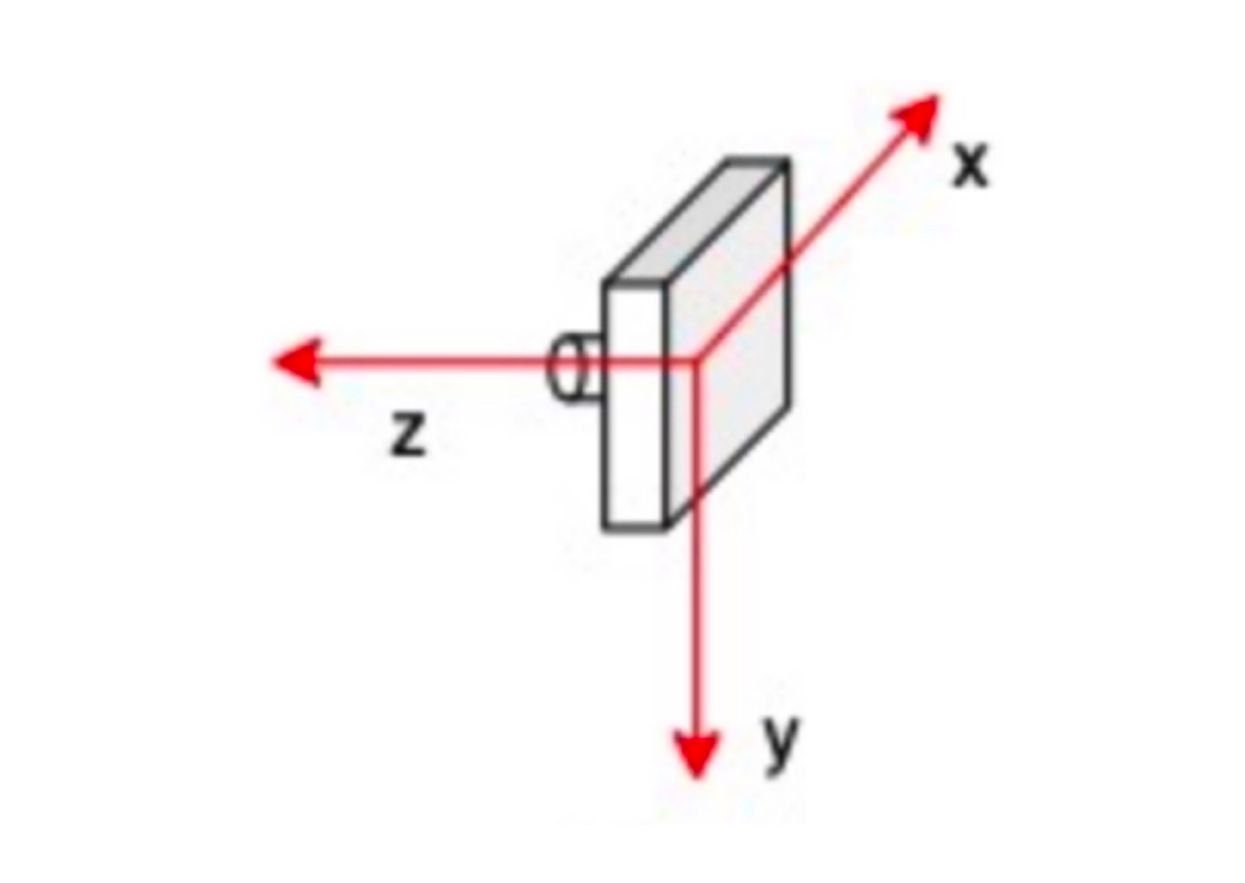
With the camera as the origin, we can create another 3D coordinate system:
- Origin: the center of the camera device (approximate)
- X-axis: the right side of the camera
- Y-axis: below the camera
- Z-axis: the front of the camera
P=(Xc, Yc, Zc) are the coordinates of a 3D point in point cloud data.
NotesThis is a transitional coordinate system, with axis units in meters, not pixels.
🏞️ **Image/Pixel Coordinate System (2D)**
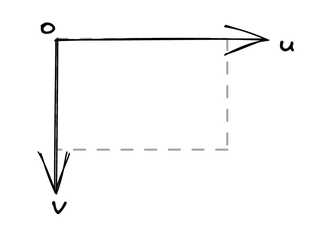
This is a 2D coordinate system based on the upper left corner of the image:
- Origin: the top left corner of the image
- U(X)-axis: from left to right
- V(Y)-axis: from top to bottom
P=(u,v) are the coordinates of a 2D point in image data.
NotesIn some references, the image and pixel coordinate systems are considered two separate systems, but in the BasicAI fusion annotation tool, we merge them for practical reasons.
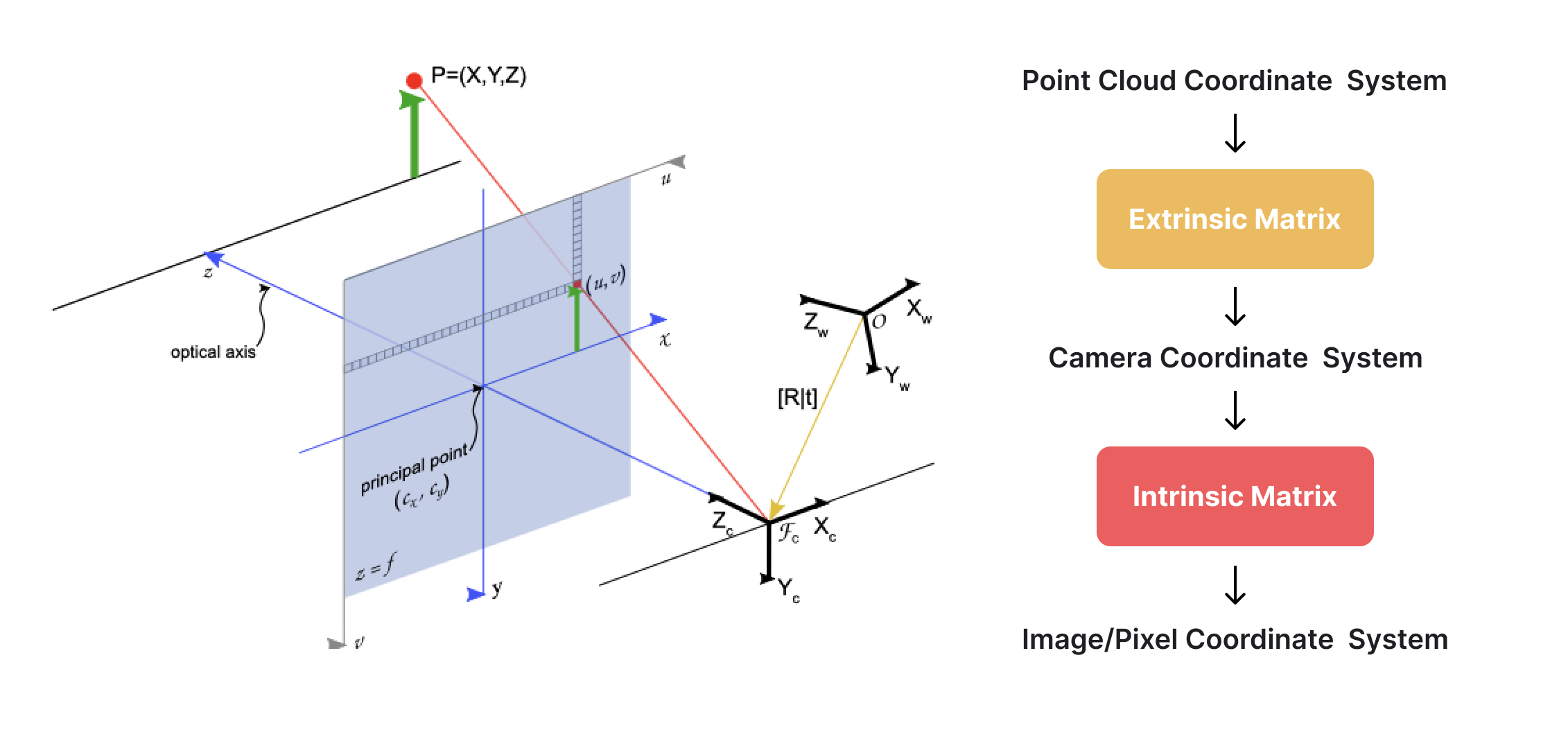
Mapping 3D LiDAR points to pixels in the 2D images involves the transformations of these coordinate systems, which consists of two steps:
Step 1: Transform the point's coordinates from the point cloud coordinate system (3D) to the camera coordinate system (3D)
Step 2: Simulate the photo-taking process to convert the point from the camera coordinate system (3D) to the image/pixel coordinate system (2D).
Camera calibration, also known as camera resectioning, estimates the parameters (in matrices) of these transformation processes. The transformation matrix in Step 1 is known as the extrinsic matrix, while the transformation matrix in Step 2 is referred to as the intrinsic matrix.
Extrinsic Matrix
The first step will be to transform the point's coordinates from the point cloud coordinate system (3D) to the camera coordinate system (3D).
This process is similar to explaining directions to someone. You can't directly say "go left" or "go right" based on your current position and direction, but you have to presume their position and direction, and then you can tell them to go left or right.
Consider you as a point cloud coordinate system and someone as a camera coordinate system. Your presumption about their position and direction contains translation (T) and rotation (R) based on you, which is called extrinsic parameters in camera calibration.
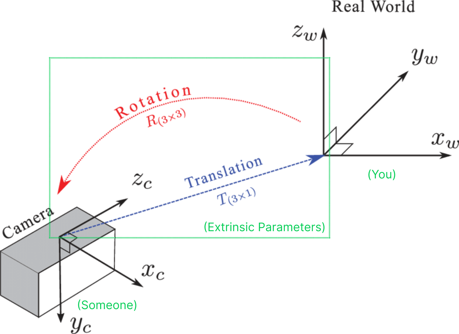
Extrinsic parameters have different representations, varying in transform direction and the rotation(R) part. In BasicAI, we use the extrinsic matrix to depict the radar-to-camera coordinate transformation parameters.
Extrinsic Matrix is a 4x4 matrix with the following form:
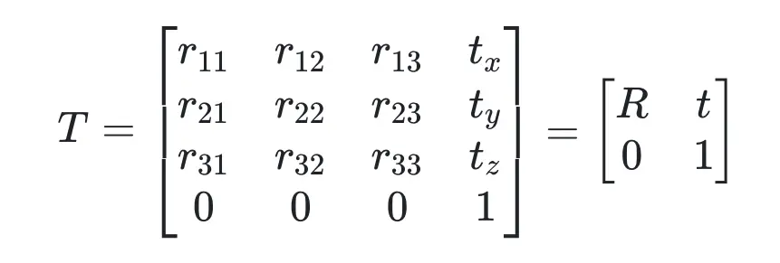
where R represents a 3x3 rotation matrix and t represents a 3x1 translation vector.
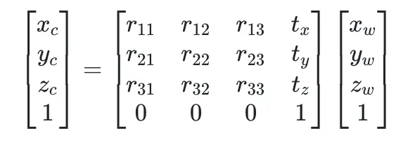
Assume a point Pw=(Xw, Yw, Zw) in the radar coordinate system (3D) is projected into a point Pc=(Xc, Yc, Zc) in the camera coordinate system (3D). The transformation process Pc=T x Pw can be expressed as:
In Python code, it is expressed as:
import numpy as np

# Assume some arbitrary values for the variables
r11, r12, r13 = 0.1, 0.2, 0.3
r21, r22, r23 = 0.4, 0.5, 0.6
r31, r32, r33 = 0.7, 0.8, 0.9
tx, ty, tz = 1.0, 2.0, 3.0
x, y, z = 4.0, 5.0, 6.0
# Construct the transformation matrix T

T = np.array([
    [r11, r12, r13, tx],
    [r21, r22, r23, ty],
    [r31, r32, r33, tz],
    [0,   0,   0,   1],
])

# Construct the 3D point
p = np.array([x, y, z, 1])

# Perform the matrix multiplication
p_ = T @ p

print(f"Camera coordinates point p_ = {p_}")
#Camera coordinates point p_ = [ 4.2  9.7 15.2  1. ]
In BasicAI, you simply need to upload the extrinsic parameters within the camera config JSON. The matrix is presented in the following format:
"camera_external": [
    0.1, //r11
    0.2, //r12
    0.3, //r13
    1.0, //tx
    0.4, //r21
    0.5, //r22
    0.6, //r23
    2.0, //ty
    0.7, //r31
    0.8, //r32
    0.9, //r33
    3.0, //tz
    0,
    0,
    0,
    1
],
The comments here are purely for illustration; please don't use them in your camera config JSON.
Intrinsic Matrix
Intrinsic Matrix, also known as the camera intrinsic parameter matrix, describes some of the physical properties of the camera lens. It is a 3x3 matrix with the following form:
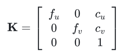
- fu and fv (fx and fy): These two parameters are the focal length of the camera, usually in pixels. fx for the x-direction and fy for the y-direction. Ideally, fx and fy should be equal, as most cameras have square pixels. However, in practical applications, they may differ due to reasons such as lens distortion and manufacturing errors.
- cu and cv (cx and cy): These two parameters are the coordinates of the image center (principal point). Ideally, the principal point should be at the exact center of the image. However, in practice, it may deviate due to various reasons (e.g., lens shift, manufacturing error, etc.).
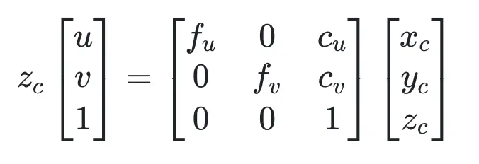
Convert a point Pc=(Xc, Yc, Zc) in the camera coordinate system to a point Pi=(u,v) in the image/pixel coordinate system. The transformation process can be expressed as:
In Python code, it is expressed as:
import numpy as np

# Assume some arbitrary values for the variables
fx = 500.0  # focal length in x direction, here we assume fx=fu
fy = 500.0  # focal length in y direction, here we assume fy=fv
cx = 320.0  # principal point in x direction, here we assume cx=cu
cy = 240.0  # principal point in y direction, here we assume cy=cv

# Construct the camera matrix K
K = np.array([
    [fx,  0,  cx],
    [0,  fy,  cy],
    [0,   0,   1]
])

#Camera coordinates point
p_ = [4.2, 9.7, 15.2, 1.]

# Perform the matrix multiplication
xyz = K @ p_[:3]

# Normalize the coordinates
x, y = xyz[:2] / xyz[2]

print(f"x = {x}, y = {y}")
# The final result will be x = 458.15789473684214, y = 559.078947368421
In BasicAI, you simply need to upload the intrinsic parameters within the camera config JSON. The matrix is presented in the following format:
"camera_internal": {
    "fx": 500.0,
    "cx": 320.0,
    "fy": 500.0,
    "cy": 240.0
}
Distortion Coefficients
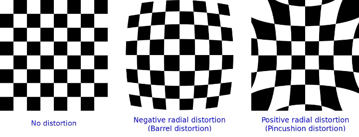
Real lenses usually deviate from the ideal pinhole camera model, introducing significant distortion to images. As a result, camera parameters include Distortion Coefficients in addition to intrinsics and extrinsics. The main types of distortion are radial distortion and tangential distortion.
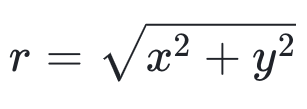
Radial distortion causes straight lines to warp, increasing with distance from the image center.
The radial-distorted points are denoted as (xd, yd):
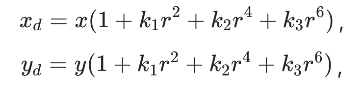
where **kn (n ≤ 8 in BasicAI) are radial distortion coefficients and
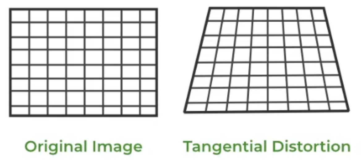
Tangential distortion occurs when the lens is not aligned perfectly parallel to the imaging plane. As a result, some areas in the image may appear closer than expected.
The tangential-distorted points are denoted as (xd, yd):
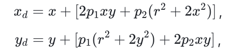
where **p1, p2 are tangential distortion coefficients and

In BasicAI, you simply need to upload the distortion coefficients within the camera config JSON, which is presented in the following format:
"distortionK": [
    -0.30912646651268,   //k1
    0.0669714063405991   //k2
],
"distortionP": [
    0.00262697599828243, //p1
    0.00106896553188562  //p2
],
The comments here are purely for illustration; please don't use them in your camera config JSON.
Practice in BasicAI 🤖
BasicAI provides a robust Lidar Fusion Tool for annotating 2D/3D sensor fusion data. Precise camera calibration parameters are essential. Kindly check the sections below or join our Slack channel for prompt support. 🙋♀️
Camera Parameter Config
When creating a LiDAR Fusion dataset, you need to upload data in a compressed file along with a camera config.
For more details about creating datasets and uploading data, please refer to Data and Folder Structure.
The parameters of each camera in the Camera config file are:
- "camera_intrinsic" or "camera_internal": a dictionary of the camera intrinsic matrix with four keys: fx, cx, fy, and cy.
- "camera_extrinsic" or "camera_external": a list of the camera extrinsic matrix obtained by converting a 4x4 extrinsic matrix into a list
- "distortionK": a list of radial distortion coefficients, only needed when your images have distortion, supports up to 6 parameters. It is optional. Delete this key when you don't need it.
- "distortionP": a list of tangential distortion coefficients, only needed when your images have distortion, supports up to 2 parameters. It is optional. Delete this key when you don't need it.
The camera configs for the 2D images corresponding to the same PCD file are stored in ONE JSON file as shown below:
Notes for camera_conf doesn't work
- Use VScode to see if your JSON has syntax errors.
- Please don't use comments in the camera config JSON
- Camera configs is an array, even if you only have one camera
- Camera extrinsic is a 4x4 matrix, not 3x3. Don't forget [0,0,0,1]
- Check the format of your camera_intrinsic and camera_extrinsic, they are easily messed up
[
  {
    "camera_external": [
      0.76866726,
      0.04361939,
      0.63815985,
      -1.59,
      -0.63870827,
      -0.00174367,
      0.76944701,
      0.91,
      0.03467555,
      -0.9990467,
      0.02651976,
      0.96,
      0,
      0,
      0,
      1
    ],
    "camera_internal": {
      "fx": 382.06535583,
      "cx": 326.66902661,
      "fy": 421.05123478,
      "cy": 254.70249315
    },
    "rowMajor": true,     // Whether external params is row major or not, default false
    "distortionK": [
      -0.30912646651268,
      0.0669714063405991
    ],
    "distortionP": [
      0.00262697599828243,
      0.00106896553188562
    ],
    "width": 1920,
    "height": 1280
  },
  {
    ....//Camera parameters of camera_1. DELETE this comment and "..." before uploading
  }
]
Manual Calibration
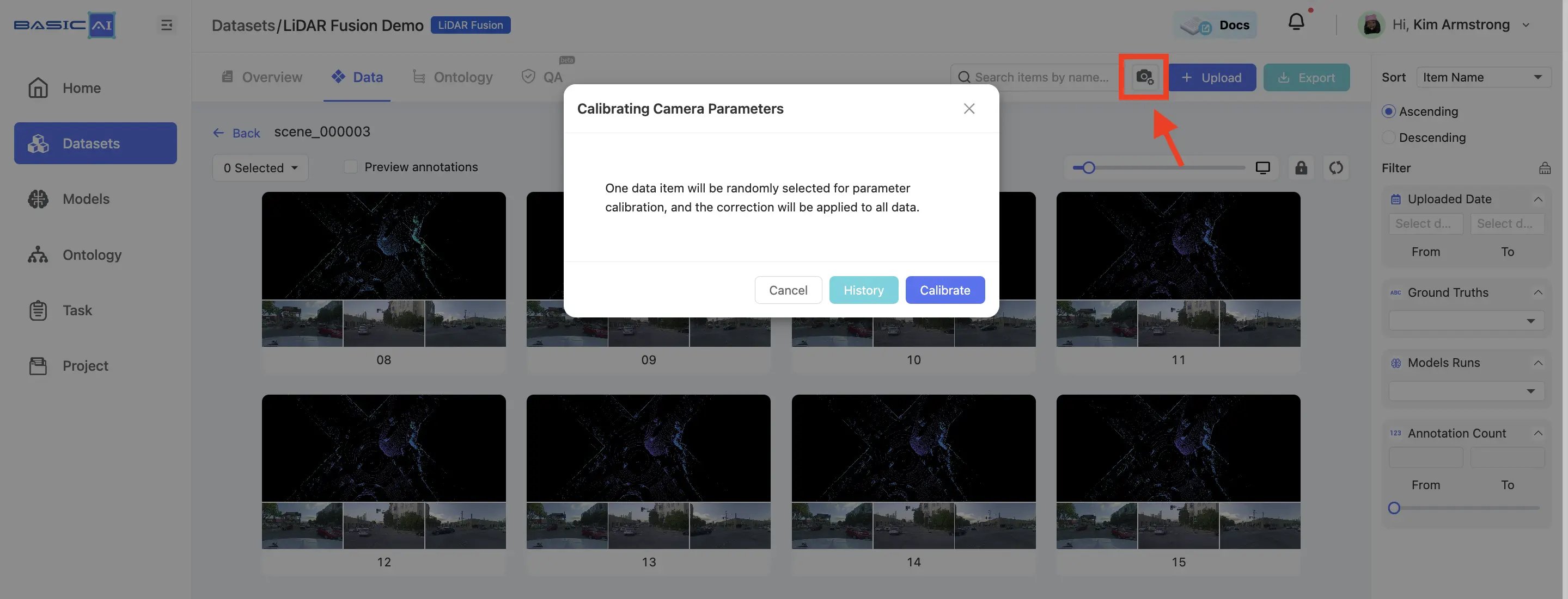
After uploading the LiDAR Fusion data and camera config, you can manually calibrate the camera parameters in the dataset.
This feature is only available if you already have camera parameters that are not very accurate. It does not work with completely absent or wildly inaccurate camera parameters.
Enter the dataset and click the Camera Calibration button located in the top-right corner. You can either create a new calibration or select an existing one here.
Select "Point" from the toolbar to annotate the point cloud data. Then, double-click on the images to adjust the positions of the projected points. Make sure that each image has at least THREE points associated with the point cloud result.
After adjusting the points, click Recalculate Calibration. Once the calibration is complete, create or project a point to verify whether the automatically mapped point positions are correct. If incorrect, readjust the positions of each pair of points in the images and point cloud.
Click the Update button located in the top-right corner to apply the current camera parameters.

Updated about 1 year ago